- When system voltage is more than the voltage rating of a single thyristor, SCRs are connected in series in a string. These, SCRs should have their V-I characteristics as close as possible.
- On account of inherent variations in their characteristics, the voltage shared by each SCR may not be equal.
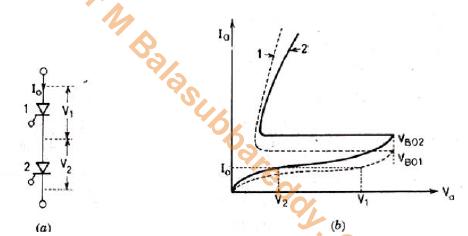
- For instant consider two SCRs with their static V-I characteristics as shown in Fig., For SCR1, leakage resistance (=V1/I0) is high whereas for SCR2, it is low (V2/I0).
- For same leakage current I0 in the series connected SCRs, SCR1 supports rated voltageV1 whereas SCR2 supports voltageV2<V1.
- Each SCR in Fig.1 is rated for a forward blocking voltage of V1 volts which is always less than its forward breakover voltage.
- Two SCRs can support a maximum voltage of V1+V2 and not the rated blocking voltage 2V1.
- A uniform voltage distribution in steady state can be achieved by connecting a suitable resistance across each SCR such that each parallel combination has the same resistance.
- This will require different value of resistance for each SCR which is a difficult proposition.
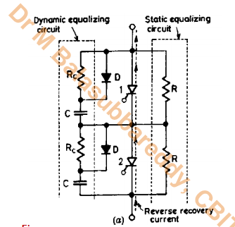
- A more practical way of obtaining a reasonable uniform voltage distribution during steady state working of series-connected SCRs is to connect the same value of shunt resistance R across each SCR as shown in Fig.2
- This shunt resistance R is called the static equalizing circuit. Magnitude of parallel resistance R can be obtained as follows.
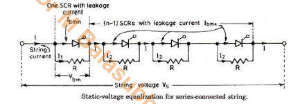
- As SCR1 has lower leakage current, it will block voltage Vbm (say) which is more than that shared by each of the other (n-1) SCRs.
- Voltage across SCR1 is Vbm . Voltage across (n-1)SCR is (n-1) I2R, So the voltage equation for the series circuit is
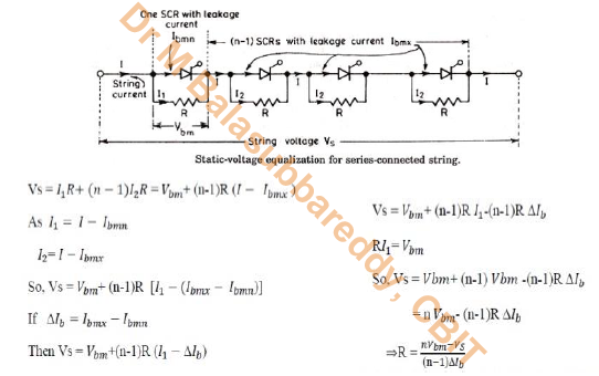
Once the value of R is calculated, its power rating is given by where Vr=rms voltage across R\

It is likely that SCRs do not have identical dynamic characteristics
In such a case, series-connected SCRs will have unequal voltage distribution during the transient conditions
The dynamic characteristics of two SCRs during turn-on are shown in Fig. a, where it is assumed that turn-on time of SCR2 is more than that of SCR1 by Δtd.
Before these two SCRs are gated, string voltage Vs is shared as Vs/2 by each thyristor. Now both SCRs are gated at same time.
As SCR1 has less turn-on time, it gets turn-on at instant t1, whereas SCR2 is yet off. Voltage across SCR1 drops from Vs/2 to almost zero.
At the same instant t1, voltage across off SCR2 will boost from Vs/2 to almost Vs. thus, the voltage shared by two SCRs are unequal.
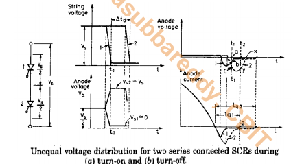
- After instant t1, voltage Vs across SCR2 may turn it on in case Vs is greater than its breakover voltage. SCR2 will, however, get turned on at time (t1+Δtd).
- During turn-off, thyristor characteristics are shown Fig.b, SCR1 is assumed to have less turn-off time tq1, than that of SCR2 .
- At instant t2, SCR1 has recovered and is passing through zero voltage whereas SCR2 is developing reverse recovery voltage xy.
- At instant t1 in Fig.b, both SCRs are developing different reverse recovery voltages given by ab for SCR1 and ac for SCR2, so the two SCRs have unequal voltages across themat t1.
- It is this seen that SCRs with different characteristics during turn-off time suffer from unequal voltage distribution during their turn-off processes.
- It may thus be concluded from above that series-connected SCRs do suffer from unequal voltage distribution across them during their turn-on and turn-off processes.
- A simple resistor for static voltage equalization cannot maintain equal voltage distribution under transient condition.
- During turn-on and turn-off, the capacitance of the reverse biased junction determines the voltage distribution across SCRs in a series connected string.
- As reverse biased junctions are likely to have different capacitances, called self capacitances,the voltage distribution during turn-on and turn-off periods would be unequal.
- Voltage equalization under this condition can, however, be achieved by employing shunt capacitors as shown in Fig.3
- In other words, during turn-on and turn-off periods, the resultant of shunt capacitance and self-capacitance of each SCR tend to be equal for each of the series connected SCRs.
- When any SCR is in the forward blocking state, the capacitor connected across it gets charged to a voltage existing across that SCR.
- When this SCR is turned on, capacitor discharges heavy current through this SCR
- For limiting this discharge current spike, a damping resistor Rc is used in series with capacitor C.
- Resistor Rc also damps out the high frequency oscillations that may arise due to the series combination of Rc, shunt capacitor and circuit inductance.
- Combination of Rc and C is called the dynamic equalizing circuit, note that the function of Rc and C is to equalize the voltage during transient conditions and to protect the thyristors against high dv/dt.
- A diode D is also place across Rc, when forward voltage appears, diode bypasses Rc during charging time of the capacitor C.
- This makes the capacitor more effective in voltage equalization and for limiting dv/dt across SCR.
- However, during capacitor discharge, Rc comes into play for limiting the current spike and rate of change of di/dt.
- In series connected SCRs, voltage unbalance during turn-off time is more predominant than it is during turn-on time.
- Therefore, choice of capacitor C is based on the reverse recovery characteristics of SCRs.
- In series connected SCRs, voltage unbalance during turn-off time is more predominant than it is during turn-on time.
- Therefore, choice of capacitor C is based on the reverse recovery characteristics of SCRs.
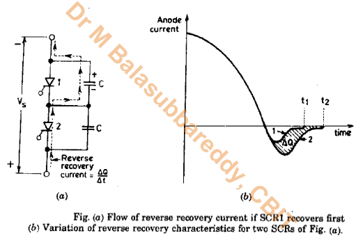
- In Fig.4b are shown reverse recovery characteristics for two SCRs of Fig. 4a.
- SCR1 is assumed to have short reverse recovery time as compared to SCRs. Shaded area ΔQ, proportional to the product of current and time, is the difference in the reverse recovery charges of two SCRs 1 and 2.
- Under this assumption, SCR1 recovers first, it therefore, goes into blocking state and does not allow the passage of excess charge ΔQ left on SCR2.
- The SCR with the least reverse recovery time will share the highest transient voltage, sayVbm .
- As stated above, the voltage difference to which the two shunt capacitors are charged during reverse recovery time is ΔQ/C, the transient voltage shared by slow thyristor 2 must beVbm-ΔQ/C.
- Voltage across fast top SCR1, V1=VbmVoltage across slow bottom SCR2 V2=Vbm- ΔQ/C.
- String voltage,Vs=V1+V2=Vbm+Vbm-ΔQ/C .
- Now consider that there are n series-connected SCRs in a string. If top SCR has characteristics like SCR1, and the remaining (n-1) SCRs have characteristics like SCR2 of Fig. 4b.

Password: Series
pdf made by Dr M Balasubbareddy