- When current required by the load is more than the rated current of a single thyristor, SCRs are connected in parallel in a string.
- For equal sharing of currents, V — I characteristics of SCRs during forward conduction must be identical as far as possible.
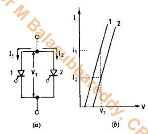
- In Fig. (a) are shown two SCRs in parallel and their characteristics during forward conduction are shown in Fig. (b).
- For parallel-connected SCRs, voltage drop VT across them must be equal. Fig. (b) shows that for the same voltage drop VT SCR1 shares a rated current I1 whereas SCR2 carries current I2 much less than the rated current I1 .
- The total current carried by the unit is I1 + I2 and not the rated current 2I1 as required.
- Now consider n parallel connected SCRs. For satisfactory operation of these SCRs, they should get turned on at the same moment.
- Consider that SCRI has large turn-on time whereas the remaining (n -1) SCRs have low turn-on time.
- Under this assumption, (n -1) SCRs will turn on first but one SCRI with longer turn on time is likely to remain off.
- The voltage drops across (n-1) SCRs falls to a low value and SCRI is therefore subjected to this low voltage.
- For a given gate drive power, anode to cathode must have some minimum forward voltage, called finger voltage, for a thyristor to turn-on.
- If voltage across SCRI drops to a value less than its finger voltage, then this thyristor will not turn on.
- Therefore, the remaining (n-1) SCRs, which are already on, will have to share the entire load current.
- As such, these SCRs may be overloaded and damaged because of heating caused by overcurrent.
- If one SCRI in a parallel unit carries more current than other SCRs, then this SCRI will have greater junction temperature rise.
- As a result, its dynamic resistance (=dVT/dIa) during forward conduction, decreases and this further increases the current shared by this SCR.
- Because of junction temperature rise, its dynamic resistance decreases and current shared by SCRI increases.
- This process of anode current rise becomes cumulative and subsequently the junction temperature of SCRI exceeds its rated value, as a result SCRI is damaged.
- This sequence of events may engulf another SCR and in this manner all SCRs in the string may be destroyed permanently.
- Therefore, when SCRs are to be operated in parallel, it should be ensured that they operate at the same temperature.
- This can be achieved by mounting the parallel unit on one common heat sink.
- Unequal current distribution in a parallel unit is also caused by the inductive effect of current carrying conductors.
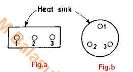
- When SCRs are arranged unsymmetrically as (a), the middle conductor will have more inductance because ofmore flux linkages from two nearby conductors.
- Consequently, less current flows through the middle SCR as compared to outer two SCRs.
- This unequal current distribution can be avoided by mounting the SCRs symmetrically on the heat sink as shown in Fig.(b).
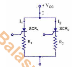
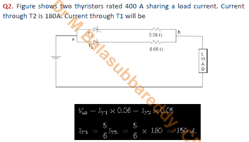
- Since external resistance R relates to each SCR, the forward voltage drops across each arm should be equal.
- Therefore, VT1+I1(R1+RT1) = VT2+I2(R2+RT2) Where R1=R2=R, RT1, RT2 are the junction resistance of SCR1 and 2 respectively.
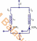
- In case of ac circuits, the current equalization can be possible with the help of inductors. Fig. shows the parallel connection of SCRs with inductive coupling.
- When the current flows through T1 and T2 are same (IT1=IT2), the voltage drop across inductance is zero due to mutual cancellation of inductance emfs in inductor L1 and L2.
- If the current flows through T1 is greater than T2 (IT1>IT2), the induced emfs in the inductive coil is directly proportional to the unbalance currents.
- Then current flow through the inductance L1 decreases but the current through the coil L2 increases. Hence, there is a tendency to share the current equally.
Password: Series
pdf made by Dr M Balasubbareddy